SYNOPSES OF SEVERAL PROJECTS DIRECTED OR DEVELOPED BY ROBERT C. MICHELSON
Select a Topic from the List Below
- INTRODUCTION
- Aerospace Radar Branch - U.S. Naval Research Laboratory
- Sirenian Tracking project [1][2][3][4]
- Attack helicopter man-in-the-loop virtual reality simulator evaluation
- Environment and Radar Operation Simulator (EROS) [5][6][7]
- Ka-Band Linear ECM Source development [8]
- FutureCar Drag Reduction empirical tests
- Development of a Coherent Repeater for testing of threat assets [13][14]
- Design and Construction of Animatronic Humans
- Development of an Indirect Fire Terminal Effects Cue [16]
- Development of a Sonar Scan Converter/Glass Cockpit for Navy Seal Swimmer Delivery Vehicles (SDV) [17]
- Design and Installation of the ASTAR Radar Forward Observer [18]
- Design of an Entomopter micro air vehicle (MAV)
- Design of an Entomopter-based Mars Surveyor [19]
- Design of a Traffic Surveillance Drone/Dragon Stalker reconnaissance vehicle
- Remote detection of buried natural gas leaks with ground penetration radar (GPR) [25]
- Radio-Acoustic Techniques for Non Line-of-Sight (NLOS) Sensing [26][27]
- Charge-Coupled Devices for Analog-to-Digital Conversion
- Design of technology demonstrations and assessment of micro air vehicle technologies
- References
INTRODUCTION
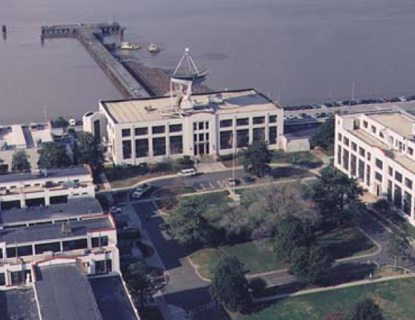
U.S. Naval Research Laboratory in Washington, D.C.
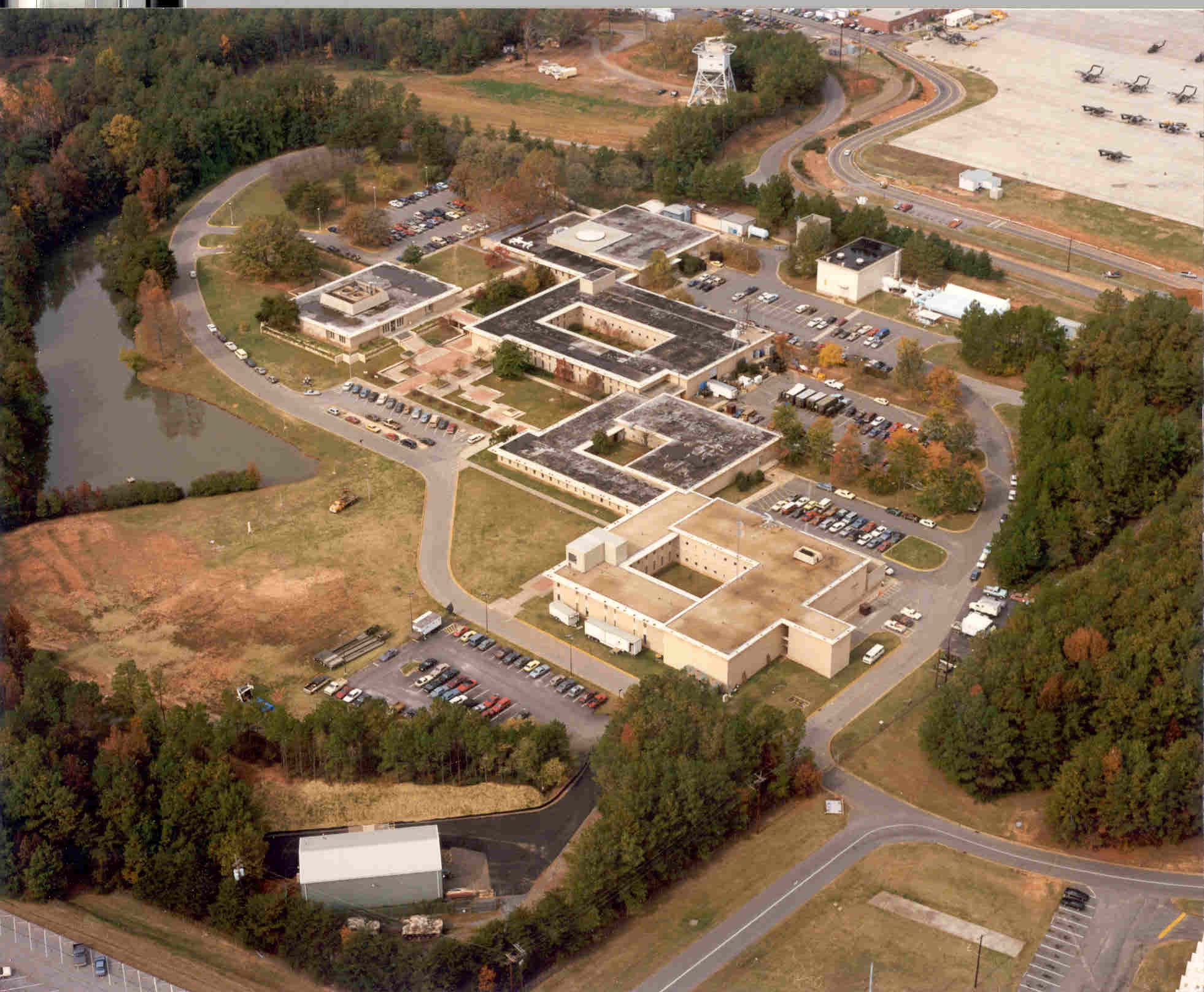
GTRI Cobb County Research Facility
During his 30-year career at the Georgia Tech Research Institute (GTRI), Prof. Robert Michelson directed over 30 major programs and contributed to scores more. Much of his project direction was conducted at the GTRI's Cobb County Research Facility near Dobbins Air Reserve Base in Georgia. Initially, Michelson worked in the former Electronics Research Building on the Georgia Tech main campus. Later his office was moved to the Baker Building when the Radar and Instrumentation Laboratory relocated operations for several years after a spate of reorganizations. Eventually the Radar and Instrumentation Laboratory moved to the remote Cobb County Research Facility where Michelson became the Head of the Instrumentation Technology Branch before joining the newly formed Aerospace and Advanced Transportation Laboratory as the Integrated Product Team Leader for unmanned aerial vehicle (UAV) systems. During his tenure at the Cobb County Research Facility, Michelson also commuted back to campus regularly to teach in the School of Aerospace Engineering.
Prior to joining the research faculty at the Georgia Institute of Technology, he participated in research programs at the U.S. Naval Research Laboratory as a member of the Aerospace Radar Branch in Washington, D.C. The following synopses briefly describe some of the programs that Michelson directed and to which he contributed. Numerous other programs can not be discussed in this forum due to restrictions on the release of details or the proprietary nature of the research.
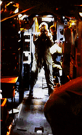
Michelson shown here finishing a camera roll after skimming the ocean to document a surface target.
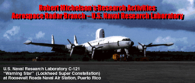
U.S. Navy super constellation number 753 mission: from Patuxent (PAX)
River Naval Air Station (Washington D.C. area), to Roosevelt Roads NAS,
Puerto Rico (with layover), and on to follow the U.S. fleet into Hurricane
Brenda while searching for other targets of opportunity before returning to
PAX River NAS via Jacksonville NAS.
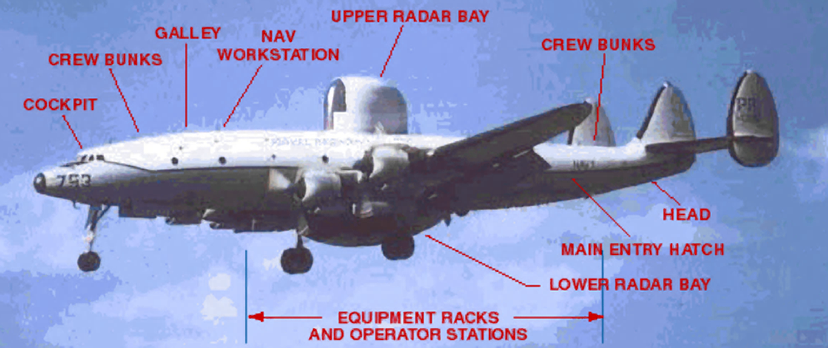
NRL Lockheed C-121 configuration.
Aerospace Radar Branch - U.S. Naval Research Laboratory
Robert Michelson was part of the research team developing and testing radar systems for ocean surveillance. Such systems would be the forerunners of present day ocean surveillance satellites. Engineering prototypes and proof of concept radars were flown in specially configured radar planes.
While on one mission in 1973, Michelson and the NRL team flew into Hurricane Brenda during a reconnaissance run. The Lockheed C-121 was also one of the first "hurricane chasers", able to penetrate the shield wall to access the eye. The Lockheed warning star began development as the US Navy PO-1W, an early model constellation airliner modified to carry experimental electronic surveillance equipment.
Several hundred aircraft were ultimately ordered by the U.S. Navy and entered service as the WV-2 and the EC-121. Throughout its life the Lockheed Warning Star was used to test experimental radar and electronic equipment installations. NRL's Lockheed C-121 was equipped with wing tanks for extended missions and had equipment racks to accommodate prototype radar systems. In latter years, this aircraft would be replaced with Navy P-3 sub-hunting airplanes. The radar system being flown on Michelson's missions was designed to simulate a dual-beam space-based radar for ocean surveillance. Typical missions involved flying at high altitude in search of either cooperative targets or targets of opportunity in the Atlantic Ocean or Caribbean Sea. Once radar data had been taken and archived, the Lockheed C-121 would drop down to low very altitude ("on the deck") to allow engineers to photograph the targets for "ground truth" analyses back in the laboratory.
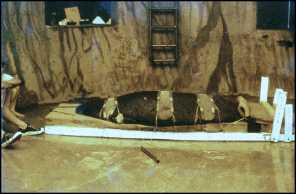
Michelson with biologists from the Florida Fish and Wildlife Service prepare to insert
an acoustic core temperature transmitter into the stomach of a recently captured
manatee found injured and transported to Marineland for recuperation.

Trichechus manatus

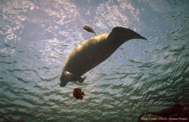
West Indian Manatee from beneath.
Sirenian Tracking Project
[1][2][3][4] The Fish and wildlife service of the U.S. Department of the Interior expressed concern over the survival of the West Indian Manatee (Trichechus manatus) and has placed it on the endangered species list. Insufficient information was available concerning the migratory habits of this species to initiate the proper steps to ensure its preservation. The population appeared to be decreasing as a result of the loss of grazing territory and an increase in boating activity. If more information were known about their numbers, location at various times of the year, mating and feeding habits, and conditions relating to their decline, the appropriate agencies could take the necessary action to enhance their survivability.
In this regard the Georgia Tech research Institute undertook a study, the purpose of which was to develop a workable concept for an automatic tracking system which would enable the Fish and Wildlife Service to determine the location and movements of manatees in order to obtain more information concerning them. This was one of Robert Michelson's first of two major programs (the other being the Radar and Operation Simulator (EROS)) that he worked on after joining the Georgia Tech Engineering Experiment Station (later renamed the "Georgia Tech Research Institute"). As a junior engineer, Michelson wrote the proposal, won a sole-source contract to perform the work, and directed a research team to satisfactorily complete the project on time and under budget.
The overall objective of this study was to perform an exploratory analysis to evaluate various existing active and passive monitoring systems of potential application to the tracking of manatees, and if the results of this study warranted further development, a follow-on effort was to be proposed.
In the execution of the study, three main requirements were set forth. First, a review of available background material and literature relevant to the technology of animal tracking was performed. Next the technical characteristics of an automatic tracking system were defined, which was capable of identifying any of various manatees in the Banana River between the Kennedy space Center crawlerway and the Bennett Causeway (State Road 528), and record each manatee's location at least once each hour. Finally, a proposal was to be prepared for the construction of the tracking system defined above with the stipulation that the system be practically expandable to monitor most of the waterways in Brevard County, Florida.
The study evaluated tracking techniques and then identified those techniques that satisfied near-term requirements as well as having growth potential for satisfying the long term requirements.
The overall performance was rated in terms of range and accuracy of measurement. Performance was intimately linked to cost which in turn was proportional to complexity when applied to electronic systems. Reliability criteria considered such factors as mean-time-between-failures (MTBF) and ease of serviceability. This included all facets of the total tracking system, both electronic and mechanical (e.g., devices for securing electronic tag to the manatee, antenna masts, etc.). Operational lifetime, size, and weight were all quantities to be optimized with trade-offs occurring between operational lifetime and size-weight limitations of the manatee-born electronics in particular. The Manatee-system interface involved a very important and largely unknown set of criteria. The objective was to modify the individual's behavior as little as possible as a result of the electronic tag. Also, extreme precautions had to be taken to assure that the tag or the tagging process had no detrimental effect on the manatee. Finally the environmental impact of each component of the tracking system had to be assessed. Not only was it undesirable to perturb the natural setting (the manatee's habitat) but man's habitat (the airwaves, boating channels, etc.) must go on abused as well.
Robert C. Michelson in Apache attack helicopter during live fire exercise. Ft. Stewart GA.
Attack helicopter Man-in-the-Loop Virtual Reality Simulator Evaluation
During the mid 1990s, Robert Michelson worked with faculty from the School of Aerospace Engineering and other industrial contractors to evaluate all of the Attack Helicopter simulators around the United States. As part of this job, Michelson got to fly all of these simulators. Some were full-motion simulators, while others use techniques to trick the senses into feeling like there was full motion when in fact, none was present. Certain simulators had advanced graphics capabilities which included eye-trackers and foveal insets to present high resolution views only where the human eye was focused at the moment, leaving peripheral vision at a lower resolution in order to reduce the bandwidth necessary to present scenes. Some of the attack helicopters (mostly Apache gunships) had actual instrument clusters while others simulated not only the exterior scenes of around the helicopter, but also the instrument panels. In all cases, there was audio input as well. Some of the simulators were "stand-alone" systems used to evaluate pilot responses, while others were networked to allow full interactive flight scenarios in which simulators could engage in battle between one another (the SIMNET system allowed helicopters to engage tank simulators and other vehicle simulators located in remote locations. For example, Ft. Knox had SIMNET tank simulators which could engage the helicopter simulators at Ft. Rucker).
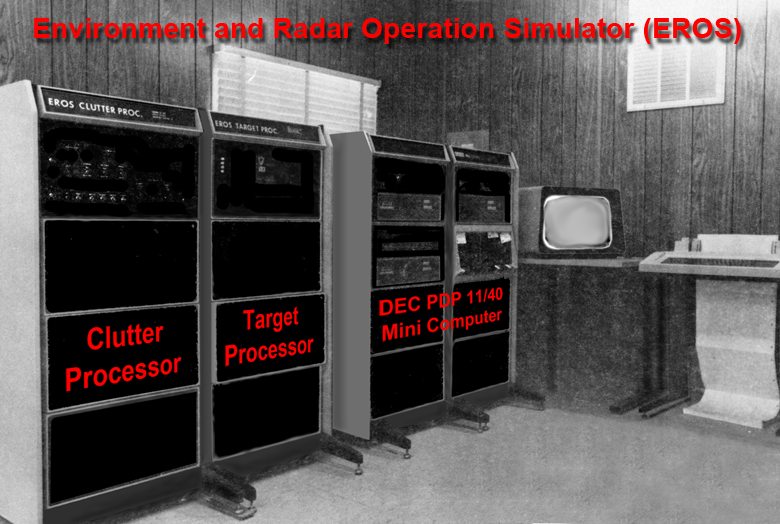
Environment and Radar Operation Simulator (EROS).
Environment and Radar Operation Simulator (EROS)
[5][6][7] The Environment and Radar Operation Simulator (EROS) was a hybrid system combining a general-purpose computer, special-purpose digital hardware, and analog hardware, which function was to produce synthetic backscatter. The simulator was electronically connected to a subject radar, and the synthetic backscatter constituted a simulation of the radar’s external world. The purpose of EROS was to reduce the cost of environment testing for battlefield surveillance radars by improving the repeatability and controllability of tests, and by replacing much of the field testing with laboratory testing. Battlefield clutter was synthesized by an array of digital filters, which provided controllable amplitude distributions, spatial distributions and spectra. Targets were simulated by combining recorded backscatter with user-defined maneuvers. EROS interacted with the subject radar by sensing its antenna scan angle and by responding in real time with the correct composite video signal.
The EROS program was conducted for the U.S. Army Electronics Research and Development Command (ERADCOM) at Ft. Monmouth, New Jersey. This was one of Robert Michelson’s first two major programs that he worked on after joining the Georgia Tech Research Faculty (the other being the Sirenian Tracking Project for which he was Project Director). On the EROS program, Michelson was in charge of the development of the “Target Processor” which involved the design of a 10 MHz target processing unit (essentially a custom 100ns cycle time special purpose computer processor. At the time, no general purpose small computers were capable of these processing speeds).
Background: At the time, in order to evaluate or compare different radar systems or signal processors, an extensive series of field tests had to be conducted. To cover the various conditions of foliage and fixed clutter, weather and terrain characteristics, several test sites had to be chosen, and even then, the test results would apply only to a specific and very limited set of conditions. Field test results, therefore, often lacked generality and repeatability.
One solution to this problem was a radar testbed which would simulate a comprehensive radar environment with high accuracy and repeatability. This system must control target size, speed, duration, clutter type and statistics, scanning and antenna pattern affects, and should include both synthetically simulated signals as well as a store of representative recordings. EROS was developed by the Georgia Institute of Technology's Engineering Experiment Station (later renamed: Georgia Tech Research Institute) as such a hardware facility.
EROS connected to a subject radar and produced synthetic backscatter which simulated the radar’s external world. The simulation scenario was completely defined by the user and included target recordings, target maneuvers, clutter spectral parameters, clutter amplitude parameters, clutter spatial dependence, antenna pattern, and range dependence. EROS interacted with the radar and radar operator by sensing the antenna scan angle and responding in real time with the correct composite backscatter.
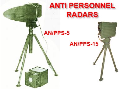
The prototype version of EROS was developed to address a specific continuous wave (CW) phase modulated, battlefield surveillance radar. However, sufficient flexibility was built in to permit simple adaptation to other battlefield surveillance radars. In particular, EROS was interfaced with the AN/PPS-15 and AN/PPS-5 antipersonnel radars.
System concepts and description: The scenario to be simulated was an annular shaped region, which represented the portion of the battlefield visible to the radar. The region was subdivided into concentric rings (at constant range from the subject radar) and radial columns (at constant azimuth with reference to the subject radar). The simulated antenna beam consisted of a contiguous set of these azimuth columns. The center of the beam was determined by sampling of a voltage from the subject radar which represented its antenna angle.
The intersection of range rings and azimuth columns defined a subdivision of the scenario into four-sided cells, which were called "simulation cells." The concept of the simulation cell was useful in providing a reference for the EROS operator in defining the scenario. Moreover, much of the internal communication between EROS components was expressed in terms of simulation cells.
The EROS hardware consisted of a digital computer, special-purpose digital hardware, and analog hardware. The computer contained a cathode ray tube graphic display unit and approximately 40 MB of online disk storage. These facilities assisted the EROS operator during scenario definition and real-time simulation by supplying control information to the digital hardware. The digital hardware, in turn, generated synthetic clutter backscatter, applied antenna pattern weighting, and combined clutter signals with target signals. The combined data were sent to the analog hardware.
The analog hardware applied range dependent weights (e.g., 1/R 4 power attenuation) and generated a video frequency signal incorporating the subject radar's transmitter modulations.
The target and clutter signals included the Doppler and radar cross section fluctuations of the simulated backscatter. In the computer and digital hardware, these were expressed in terms of sampled waveforms. Each sample was a complex quantity represented by two quadrature components of the waveforms.
Target signals in EROS were recorded on a computer disk during scenario definition. Additional target data (specified via the computer's graphic display unit) consisted of a target movement definition and a schedule of events. This information was compiled onto a disk file and was subsequently retrieved for transmission to the digital hardware during real-time simulation. The target signal strength was apportioned between two adjacent range rings to ensure realism. This technique eliminated an abrupt discontinuity (in range-gated radar reception) as the target crossed the boundary between range rings. A similar problem in azimuth boundaries was avoided by using very high resolution in the representation of the antenna pattern.
Of the various models available that describe clutter amplitude distributions, the Ricean was chosen for EROS implementation. This decision was prompted by several factors:
The Ricean density function was based on a physical model of ground clutter.
The Ricean model had widespread support in the literature as a realistic amplitude distribution model for ground clutter. It had been successfully curve-fitted to clutter measurement data taken under a variety of environmental conditions.
The assumption of a Ricean amplitude distribution made the clutter synthesis implementation manageable.
Clutter was synthesized in the digital hardware by applying pseudo-random sequences (digital noise) to digital filters. The output from the filters had spectra and amplitude distributions that were controllable as functions of the filters parameters. The simulated return for the moving portion of clutter was synthesized by two identical 2-pole filters which generated the two quadrature components. The return for the fixed portion of the clutter was simply a complex constant.
The range profile was recomputed at the Doppler sampling frequency that was several times slower than the pulse-repetition frequency (PRF) of the subject radar. The digital hardware stored each range profile in a random access memory (RAM) and this data was retrieved at the PRF; several repetitions of the same data were used before a new range profile was stored.
The range profile was sent to the analog hardware at the PRF rate. Each transmission was delayed a fixed interval after the radar's pulse trigger; this delay corresponded to the distance between the radar and the closest simulated range. The range samples were sent in ascending range order. The interval between samples corresponded to the width of the simulated range rings. Each range sample was accompanied by a corresponding range-dependent attenuation. After the transmission of the range sample for the most distant ring, the digital hardware waited for the trigger denoting the next radar pulse.
The digital hardware performed those functions where the speed and the number of computations were beyond the real-time capability of the computer. Filter parameters, azimuth weights, and the current azimuth position for clutter, as well as signal samples, and range and azimuth weights for targets were supplied by the computer to the digital hardware.
The clutter processor continuously calculated synthetic clutter backscatter for the 544 cells in the currently simulated antenna beam. Each Doppler sampling cycle consisted of performing one computation step for each filter, applying the antenna pattern weights, and performing azimuth integration.
The target processor applied the azimuth weight to the two quadrature components of each target sample and stored the products with the associated range ring number in a random access memory. In general, to such sets of data were required for each Doppler sampling cycle, because part of the target sample was allocated to one range ring and the balance was allocated to the adjacent range ring. The RAM was capable of storing data for 128 Doppler sampling cycles. Status bits were stored in the RAM to denote the end of each Doppler sampling cycle and the end of 128 Doppler sampling cycles. Two such RAM memories were used, so that the computer was able to load one of them while the target processor retrieved previously loaded data from the other one. Each retrieved sample was added to the clutter range profile at the range specified by the retrieved range ring number.
The video signal was produced by storing each range profile in RAM memory and by reading it back at the radar’s pulse repetition frequency. Three 12-bit D/A converters received the digital information in real time. These modules converted the “I components” and “Q components” and range weights at a rate of up to 10 MHz (which corresponds to a 15 m range ring in round trip propagation). The range weights were applied to each of the video signals in separate analog multipliers. For the original CW radar application, the outputs of the multipliers were integrated in analog integrators that were reset periodically by pulses coincidental with the transmitter modulation. Since signals from all range rings were present for equal time increments, integration with respect to time was equivalent to algebraic addition of the data from successive range rings. For the pulsed radar application, the integrators were switched out. An adjustable amount of simulated receiver noise was finally added to the signals before they were transmitted to the radar.
Summary of EROS parameters: The maximum video sampling rate equaled 10 MHz, corresponding to a range ring width of 15 m, and a maximum Doppler sampling rate of 4545 Hz. The number of simulated range rings was 64 and the total simulated range was 960 m. The total simulated azimuth was 360° with an instantaneous simulated azimuth of 22.5°. The target range resolution was 15 m, and the target azimuth resolution was 0.0027°. The clutter cell size was 30 m x 1 .4°, and the total number of clutter cells was 8192, with 544 instantaneous clutter cells stimulated. The clutter model statistics were independently selectable in each cell. A Ricean amplitude distribution was used. The antenna model and the propagation models were both user defined.
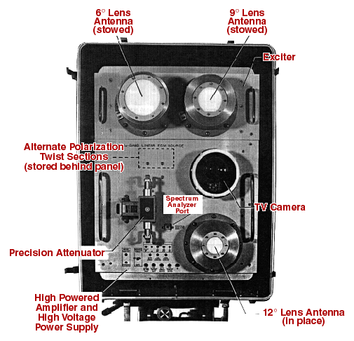
KABLES ECM test source
Ka-Band Linear ECM Source Development
[8] From 1983-84, Robert Michelson led a research team developing a KA-Band Linear ECM source (KABLES). The system was capable of amplifying a wide variety of electronic countermeasures (ECM) waveforms over a relatively wide bandwidth (33 to 37 GHz). The equipment was portable and remotely operable from a distance of 100 feet. The system was configured to operate on various manual and automatic tracking pedestals. The output power was developed by precise phase matched power addition from eight 10W KA-Band traveling wave tube amplifiers (TWTA). The radiated power was variable from zero to approximately the sum of the individual TWTA output powers (ideal 80W CW) at any one of four antenna beamwidths and with several polarizations. The signal from the exciter was precisely split eight ways in a phase matched magic tee network with semirigid coaxial phase matching lines. This unit was used to test various assets at the White Sands Missile Range.
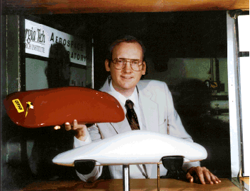
Robert Michelson in the GTRI Cobb County Research Facility low speed wind tunnel with two models of FutureCar
FutureCar Drag Reduction Empirical Tests
The future car project was done as part of the GTRI IRAD program in which a team of senior researchers directed by Robert C. Michelson considered various aspects of highly advanced electric vehicle concept known as "FutureCar". Michelson conceived FutureCar as a testbed for disparate technologies that could be integrated to produce a highly efficient and safe vehicle.
The FutureCar was envisioned as being an electronically driven exoskeleton of carbon composite (no frame) housing passive magnetic bearings; active electromagnetic suspension; virtual Windows (no glass); impact thrust -absorbing passenger compartment; actively blown surfaces for aerodynamic control; and regenerative energy-recouping schemes.
The GTRI IRAD program funded the investigation of actively blown surfaces that proved not only to be a source of lateral control, but also resulted in lower drag that theoretically possible for this body shape.
Michelson also directed a project to develop an electric vehicle system simulation for the Defense Advanced Research Projects Agency (DARPA) under a contract administered through the Southern Coalition for Advanced Transportation.[9] This program spawned other electric vehicle work and ultimately resulted in one of Michelson's patents for a pulsed battery charging technique.[10] Michelson also worked with on various other ground vehicle programs including designs for automated light-weight truck-mounted drilling rigs.[11] [12]
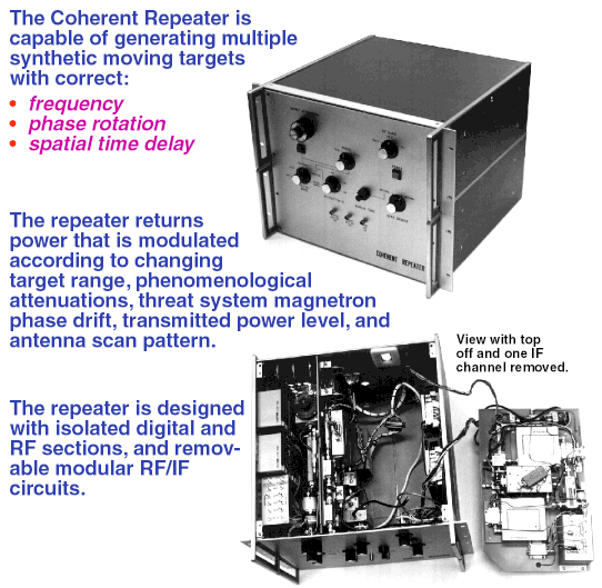
Coherent Repeater disassembled to show various component sections.
Not shown is the digital controller or Hewlett Packard signal generator which provided input to the repeater.
Development of a Coherent Repeater for Testing of Threat Assets
[13][14] During 1981, Robert C. Michelson directed and contributed technically to a U.S. Defense Department program that implemented a coherent repeater for the automated non-invasive testing of acquired Soviet threat systems. This quick reaction hardware program- as extensive, and notably more complex than any instrumentation radar that had been built by GTRI at that time- was designed, built, fully documented for remanufacture, and delivered in a period of six months. For eight years this equipment remained in service outside the United States by a foreign power. In 1990, it was returned by that government for refurbishment and upgrade by Michelson and those remaining on his original design team. It was then returned to service in 1990.
The coherent repeater was capable of generating multiple synthetic moving targets with correct frequency, phase rotation, and spatial time delay. The repeater was designed to return power that is modulated according to changing target range, phenomenological attenuations, threat system magnetron phase drift, transmitted power level, and antenna scan pattern. The repeater was designed with isolated digital and RF sections, and removable modular RF/IF circuits. A Hewlett Packard signal generator acted as a stable variable frequency source under the control of an AIM-65 based controller.
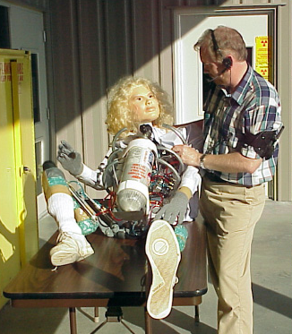
Creator, Robert Michelson with "Anna Matron", one of his pneumatic synthetic humans.
Design and Construction of Animatronic Humans
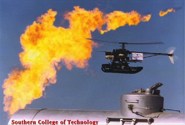
During the third mission of the International Aerial Robotics Competition (IARC) Robert C. Michelson developed a series of animatronic robots to simulate injured humans in the aftermath of a disaster. The third mission was begun in 1998. It was a search and rescue mission requiring fully autonomous robots to take off, fly to a disaster area and search for survivors and the dead amid raging fires, broken water mains, clouds of toxic gas, and rubble from destroyed buildings. The scenario was recreated at the U.S. Department of Energy's Hazardous Material Management and Emergency Response (HAMMER) training facility where the above hazards could be recreated. Because of the realism of the scenario, animatrons were used instead of human actors to simulate survivors incapable of extracting themselves from the disaster area.
An aerial robot from Germany's Technische Universität Berlin was able to detect and avoid all of the obstacles (many of which could have destroyed the robot itself), identify all the dead on the ground and the survivors (distinguishing between the two based on movement), and relay pictures of the survivors along with their locations back to first responders who would attempt a rescue[15]. This mission was completed in 2000.
During the third mission of the IARC, the disaster scene was replicated with highly unstructured and unpredictable events. The autonomous robots had to be robust enough to operate in this real environment that contained wreckage, fire, smoke and aerosols, acoustic shock waves, motion on the ground and in the air, as well as unbriefed obstacles.
The targets of the aerial robots were injured humans on the ground that were simulated by animatronic synthetics capable of limited limb motion. All simulated survivors were incapacitated and unable to move to safety under their own power. These synthetics were programmed to expire at a predetermined interval unknown to the aerial robotics teams. The number of injured humans and their location relative to the disaster scene was unknown.
Because an actual disaster scene was replicated, using 40 foot flames leaping into the air from ruptured gas mains, geysers from broken water mains, as well as smoke and aerosols, actual humans were restricted from entering the competition arena. In order to simulate injured humans, animatronic robots were created by Michelson as a target for the incoming aerial robots. The fidelity of these animatrons had to be sufficiently realistic in order to simulate actual humans so that the sophistication of the autonomous aerial robotic sensors could be tested adequately.
Michelson developed a series of animatronic robotic humans, beginning with electrical models, and ultimately developing fully articulated untethered pneumatic animatrons as his most sophisticated creations.
Pneumatic launcher used to project man-safe "flash/bang/smoke" projectiles.
Development of an Indirect Fire Terminal Effects Cue
[16] Wind tunnel model of an early projectile design with air brakes.
The objective evaluation of military tactics and doctrine requires scientifically controlled experiments of free play war game exercises in a simulated battlefield environment. The support for such field experiments requires a sophisticated range instrumentation and data collection system. It also requires a realistic simulation of the weapon systems (in a manner that is player-safe) to preserve realism for the player elements. The U.S. Army Combat Development Experimentation Command (USACDEC) at Fort Hunter-Liggett, California, has established a facility of this type for use with dismounted players, vehicle mounted players, and player and weapon elements that are airborne on helicopters, and combat aircraft.
Direct fire weapons have been effectively simulated at the Fort Hunter-Liggett test range through the use of co-boresighted laser devices that are attached to weapon barrels. These simulator devices trigger electronic casualty assessment devices located on other player elements at weapon-to-target ranges is equivalent to the normal operation of the weapon being simulated. The laser simulation system is triggered for small arms fire by the firing of a blank cartridge in the weapon (e.g., Multiple Integrated Laser Engagement System (MILES) and the Infantry Direct Fire Simulaiton System (IDFSS) programs). With larger weapons such as TOW launchers or a tank guns, the event of a firing may or may not be accompanied by a simulation of the firing signature (a flash/bang/smoke signature from a weapon effect simulator located at the launch site).
The simulated battlefield scenario addresses many of the weapons systems encountered in actual battlefield situations, but it does not include a simulation and casualty assessment for indirect fire weapons (howitzers, mortars, etc.). Indirect fire weapons may be used for inflicting casualties on opposing forces or for troop suppression. Inclusion of this important area of weapon technology is highly desirable to develop a realistic an accurate simulation of a battlefield environment. The relatively high trajectory and long firing range of the indirect fire weapon class does not allow the laser illuminator to be used as it is with a direct fire system.
The overall objective of this research directed by Robert Michelson, was to perform an exploratory analysis of various methods to accurately and remotely place a cue in a predetermined area. This cue had to automatically and simultaneously deliver a triple signature display involving a brief but intense flash of light and audible impulse, as well as the deployment of a gaseous or particulate smoke. All facets of the system were investigated with regard to their potential for causing injury to the operator, players, or observers. Attention was also given to the environmental impact resulting from the presence and use of the system. Several launcher categories were investigated to arrive at three worthy of implementation and evaluation. A catapult, rifle grenade, and pneumatic "blowgun" were constructed, tested, and evaluated with the pneumatic launcher proving most desirable. A feasibility model pneumatic launcher (based on the design of the evaluation model) was then constructed and used in the development of the feasibility model projectile.
The feasibility model launcher was able to project a relatively man safe, fire safe project goals in excess of 200 m with a circular error probable (CEP) that was far better than that required by the contract statement of work. This performance was consistently displayed during development and during the final acceptance test. The feasibility model launcher operated on the pneumatic principle of the blowgun using vaporized liquid CO2 as a propellant. An explosive flapper valve was used to transfer pressurized CO2 gas from an intermediate holding reservoir into the barrel of the launcher in which a projectile had been placed. The expanding CO2 gas was capable of ejecting a 2 to 3 ounce projectile from the barrel and hurling it in excess of 200 m using CO2 reservoir pressures as low as 30 PSIG.
The feasibility model projectile was the result of both empirical and wind tunnel analyses. The projectile carried a flash/bang/smoke cue to maximum launcher range in a relatively man's safe fashion. The feasibility model projectile was cylindrical with a flat-end tail and a hemispherical nose cone. Sophisticated surface texture techniques were used to achieve flight stability.
Catapult Prototype Launcher
Components of the Man-Safe Flash/Bang/Smoke Projectile
Wind Tunnel Model of an Early Projectile Design with Air Brakes.
The flash/bang/smoke unit contained within the projectile was engineered to deliver a triple-signature display consisting of an intense flash of light, and acoustic impulse, and a cold particulate smoke. The respective signatures of the round were limited to safety bounds established by the U.S. Surgeon General where applicable, and where no guidelines were available, safety limits were justified and established through experimentation and consultation with medical specialists. Fire safety was enhanced through the use of a cold ejected particulate smoke, high-efficiency light generation with double and triple light emitting transmitting heat blocking barriers to minimize heat leakage to the environment, and encapsulated, self-extinguishing, or fireproof projectile and flash/bang/smoke unit components.
Special attention was given to simplicity of design to facilitate mass production of system components, in particular, the expendable components comprising the projectile. Plastic molding and casting procedures were developed to demonstrate the mass predicability of the feasibility model projectiles in order to accurately estimate the cost involved in projectile manufacturere.
Catapult Prototype Launcher
Components of the Man-Safe Flash/Bang/Smoke Projectile
Wind Tunnel Model of an Early Projectile Design with Air Brakes.
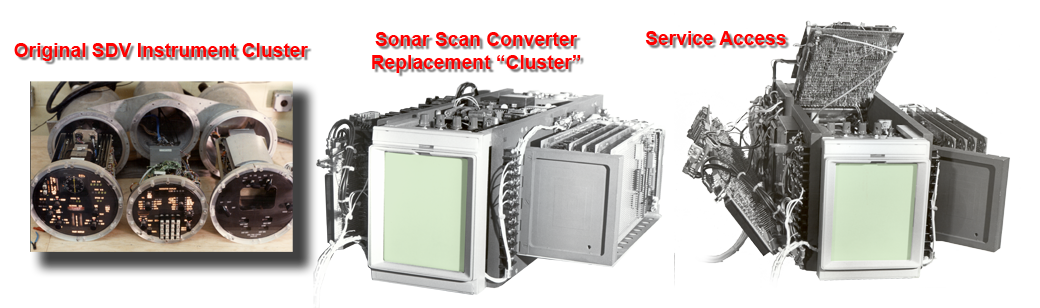
Sonar Scan Converter and the instruments that it would replace.
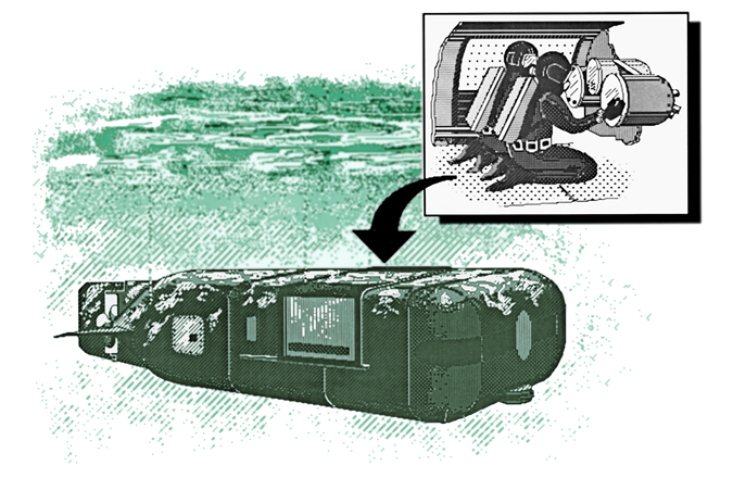
Development of a Sonar Scan Converter/Glass Cockpit for Navy Seal Swimmer Delivery Vehicles (SDV)
[17] Robert Michelson directed a developmental program for the U.S. Naval Coastal Systems Center in Panama City, Florida to develop and advanced "glass cockpit" for the SEAL Delivery Vehicle (SDV). The SDV is a manned submersible and a type of Swimmer Delivery Vehicle used to deliver United States Navy SEALs and their equipment for special operations missions. It is a "wet sub". SDVs carry a pilot, co-pilot, and combat swimmer team and their equipment to and from maritime mission objectives on land or at sea. The pilot and co-pilot are often a part of the fighting team.
SEAL Swimmer Delivery Vehicle (SDV).
The SDV has compressed air to extend the range of a swimmer's own air tank or rebreather. The SDV is used primarily for covert or clandestine missions to denied access areas (either held by hostile forces or where military activity would draw notice).
The original instrument cluster for the SDV contained numerous "black box" systems to provide navigation, obstacle avoidance sonar, and vehicle status readouts and controls. All of these items were contained in a set of three aluminum pressure canisters. The "Sonar Scan Converter" developed by Michelson's team at the Georgia Tech Research Institute essentially replaced the majority of the black boxes and presented this information in a "glass cockpit" format.
The sonar scan converter was able to present a forward sector scan display of the sonar returns on a cathode ray tube (CRT) screen with the ability to view targets at various ranges by selecting delay timing scales. The scan converter took the incoming analog sonar signals and converted them to a raster scanned display upon which text could be overlaid to indicate scales and other cogent information formerly presented on a host of individual displays. This included such items as depth, magnetic heading, and various SDV status indicators. The information displayed was in both analog format (e.g., plan position indicator (PPI) sector scan for the sonar information and bar graphs for depth indication or heading) as well as textual information for specific quantities such as speed, air pressure, or remaining energy.
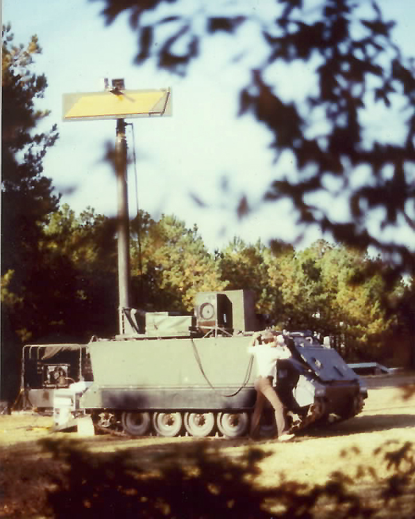
ASTAR system deployed on an M-113 armored personel carrier with pneumatic mast.
Design and Installation of the ASTAR Radar Forward Observer
[18] Under contract to the U.S. Army Combat Surveillance and Target Acquisition Laboratory, the Georgia Tech Research Institute performed a field test with the Advanced Surveillance and Target Acquisition Radar (ASTAR) prototype. The ASTAR brassboard system was integrated together under two previous contracts which included both hardware and software design, fabrication, and laboratory testing. Specifically, during the 1979 contract, the ASTAR was assembled with mostly off-the-shelf components. An AN/PPS-5 radar was modified to have a narrow beamwidth antenna (0.7°), a radar receiver made coherent-on-receive, and a radar control unit which included a moving target indicator (MTI) processor which was provided as government-furnished-equipment to the Georgia Tech research Institute. The Georgia Tech Research Institute interfaced the computer to the radar control unit, plasma display, and digital message device. Software was generated which gave the system the ability to manually detect and track targets (one axis at a time). The system was tested at Fort Sill, Oklahoma, during the Human Engineering Laboratory Battalion Tests (HELBAT-7).
The HELBAT-7 tests indicated that added sophistication was needed. The follow-on 1980 contract led to the design, fabrication, and laboratory testing of the radar interface unit which formed the central network for a distributed processing system architecture. New automatic target detection and track-while-scan (TWS) algorithms were designed and implemented in software. The narrow beamwidth antenna was replaced with a very low sidelobe slotted array antenna. A pneumatic mast assembly and an armored personnel carrier (APC) was provided to the Georgia Tech Research Institute. The ASTAR was reconfigured into a highly mobile system where the antenna, transmitter, receiver, and servo/pedestal assembly was interfaced to the mast assembly and the remaining components were reconfigured into a rack assembly located inside the APC. Limited field testing was performed on the fully assembled ASTAR brassboard system during the 1980 contractual period.
The final contract determined the ASTAR track-while-scan performance capabilities. The system was also reassembled onto a diesel engine powered APC in place of the original gasoline engine APC.
The Georgia Tech Research Institute completed the ASTAR system test and evaluation in the field using controlled targets. The ASTAR was situated on top of Turkey Mountain, Rome, Georgia. The Richard B. Russell Airport, located near Rome, provided a location where controlled targets (augmented van and pickup truck) could travel known paths up and down the runway and taxi ways, i.e., known range, angle, and speed. The controlled targets were 4.7 to 6.1 km from the ASTAR.

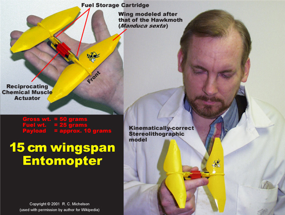
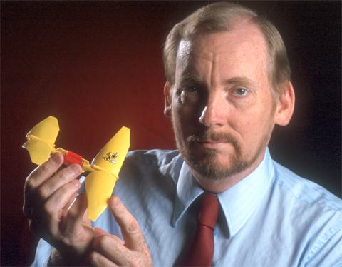
Terrestrial Entomopter stereolithographic model with 15cm wing span.
Design of an Entomopter Micro Air Vehicle (MAV)
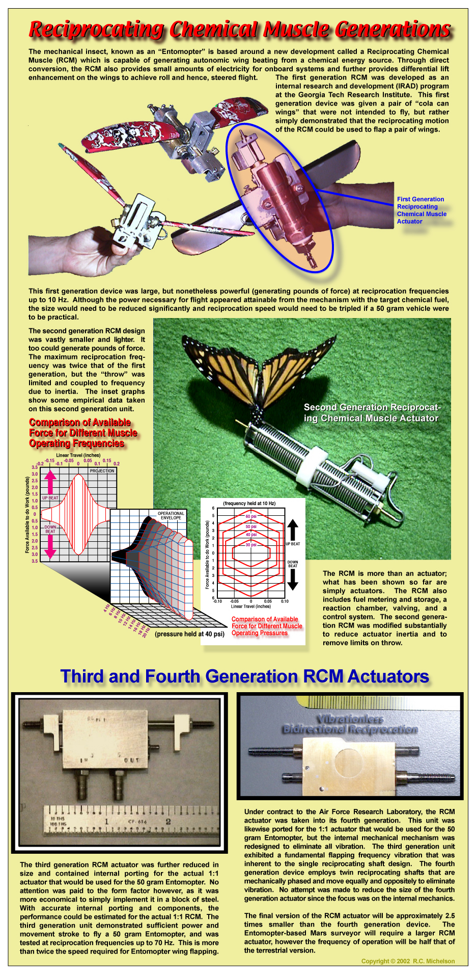
The Entomopter is a multimode (flying/crawling) insect-like robot developed by Prof. Robert C. Michelson and his design team from the Georgia Tech Research Institute (GTRI), University of Cambridge (England), ETS Labs and others. The name 'Entomopter' is derived from entomo (meaning insect: as in entomology) + pteron (meaning wing). Michelson's Entomopter is a type of "ornithopter", which is the broader term for any device intended to fly by flapping wings.
The Entomopter is propelled by a pair of flapping wings driven by a Reciprocating Chemical Muscle (RCM) which is capable of generating autonomic wing beating from a chemical energy source without an ignition source, combustion, or atmospheric oxygen. Through direct conversion, the RCM also provides small amounts of electricity for onboard systems and further provides differential lift enhancement on the wings through circulation control (Coanda effect) to achieve pitch, roll, yaw, and heave to effect steered flight.
The Entomopter performs obstacle avoidance and altimetry through the use of a frequency modulated continuous wave (FMCW) acoustic transmission created from the waste gas product from fuel decomposition within the RCM. This waste gas is also used for gas bearings (dry lubrication) of all moving parts as well as the circulation controlled "blowing" of the wings for stability control and navigation.
The Earth-bound Entomopter has a 15 to 18 cm wing span. A twin set of wings situated fore and aft of the RCM provide balanced resonant flapping to create not only lift and thrust, but full vehicle control. Wing flapping occurs a 35 Hz constant rate. This biologically inspired aerial robot is classified as a micro air vehicle (MAV) because of its size. Mission payloads are in the range of 10 grams with a full gross takeoff weight (GTOW) of 50 grams. Intended use is for covert indoor reconnaissance or operation in confined human-inaccessible spaces.
The Entomopter project received initial internal research and development (IRAD) funding from the Georgia Institute of Technology beginning in 1996, and follow-on funding from the Defense Advanced Research Projects Agency DARPA, the Air Force Research Laboratory (AFRL) and the NASA Institute for Advanced Concepts. For endeavors related to the Entomopter, Prof. Michelson is the recipient of the 2001 Pirelli Award for the diffusion of scientific culture given by an international Jury for the “best multimedia project coming from any educational institution in the world.” He was also awarded the first ever Top Pirelli Prize (€25,000) for the work deemed best from an international field of over 1000 considered.
During the initial course of this ongoing research, two patents were generated:
U.S. Patent No. 6,082,671, July 4, 2000, “Entomopter and Method for Using Same”
U.S. Patent No. 6,446,909, September 10, 2002, “Reciprocating Chemical Muscle (RCM) and Method for Using Same”
Terrestrial Entomopter stereolithographic model with 15cm wing span.
Design of an Entomopter-based Mars Surveyor
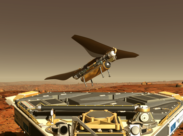
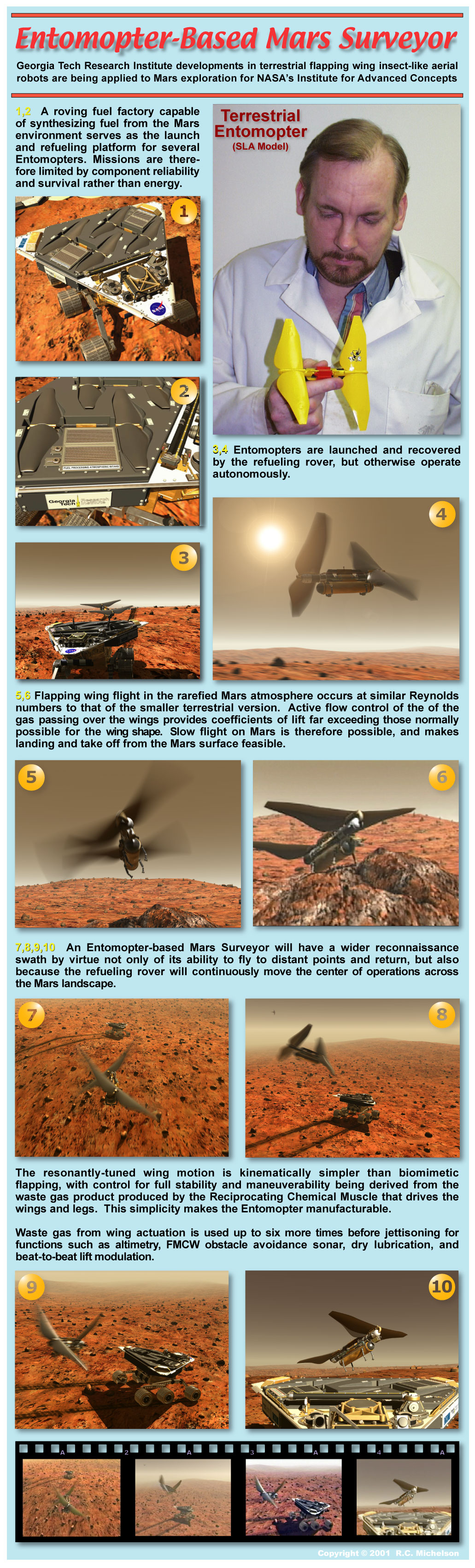
[19] From 2000 through 2002, Robert Michelson led a team at the Georgia Tech Research Institute (GTRI) that investigated mechanisms for slow flight in the lower Mars atmosphere. This work was done for the NASA Institute for Advanced Concepts, but grew out of earlier terrestrial foundations begun as GTRI internal research and development (IRAD), Defense Advance Research Projects Agency (DARPA) feasibility, and Air Force Research Laboratory (AFRL) propulsion developments. NASA determined that the unique flight qualities of Michelson's patented invention[20], the Entomopter, made it suitable for slow flight on Mars.
The first serious look at flying on Mars was done in the mid 1970s. Since then there have been numerous studies and designs for flying aircraft on Mars. Because of the very low atmospheric density on Mars all of these conventional aircraft designs have come across the same limitation, in order to generate sufficient lift the aircraft must fly fast. That fact and the rough rock strewn surface of Mars makes it almost impossible to produce a conventional aircraft that can safely land and take off again. Therefore all previously proposed aircraft missions have been limited in duration to the amount of fuel the aircraft could carry for one flight.
The Entomopter concept is a potential way around this problem of having to fly very fast within the atmosphere of Mars. The Entomopter doesn’t generate lift in the same fashion as a conventional aircraft. The Entomopter concept uses the same lift generating means that insects do on Earth to generate lift within the Mars environment. Unlike aircraft or birds, insects generate lift by the continuous formation and shedding of vortices on their wings. This vortex formation and shedding produces very high wing lift coefficients on the order of 5 compared to maximum lift coefficients of 1 to 1.2 for conventional airfoils. This very high lift generating capability is what allows insects to fly, hover and maneuver as they do. It is believed that their ability to generate these large amounts of lift is a Reynolds number based phenomena. As Reynolds number increases, the ability is diminished. This high lift generating capability under low Reynolds number flight conditions poses an interesting solution to flight on Mars. Because of the low atmospheric density on Mars, a vehicle with a wing-span on the order of 1m would be in the same flight Reynolds number regime as most insects encounter on Earth. Because of this, it is conceivable to construct a vehicle that can fly near the surface of Mars (up to 100s of meters in altitude) while generating sufficient lift to allow it to fly slow, maneuver easily, and land. This realization is the genesis for the Entomopter concept for Mars.
For the Entomopter to work within the Mars environment it will need to be as lightweight and efficient as possible. This means that systems and devices on the vehicle will need to perform more than one task if possible. This multiple use philosophy has been integral to the design effort. It begins with the propulsion system. The engine will decompose hydrazine to provide the power to move the wings. After a thorough evaluation of a number of potential fuels, hydrazine was chosen as the best candidate because of its high energy density and the fact that it is a monopropellant. Hydrazine rapidly decomposes when passed over a catalyst, thereby allowing for a low risk "combustion" scheme. The gas produced during the decomposition of hydrazine will be used to produce the wing motion through a patented[21] device called a Reciprocating Chemical Muscle actuator. Once the exhaust leaves the wing actuator, it is used for several other tribological and navigational functions before being blown out the trailing edge and tips of the wings. This gas entrainment into the flow field over the wings enables vortex stabilization and greatly enhances the lifting capacity of the wing. Wind tunnel experiments on fixed wings at the Georgia Tech Research Institute (GTRI) have shown that with the trailing edge blowing, wing lift coefficients of 10 or greater are achievable [22][23]. CFD runs corroborate the lift enhancement of the blown wing in both fixed and flapping modes [24]. In addition to lift enhancement, the trailing edge blowing will be used as a means of stability control for the Entomopter. The gas flow to each of the individual wings will be controlled to enable differential lift to be generated between the wings. To steer the Entomopter, lift variation through control of the trailing edge blowing will be used to provide banking and pitching moments.
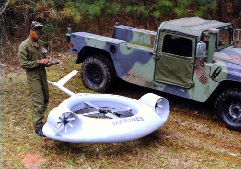
Compound ducted fan developed by Prof. Michelson's UAV team at GTRI began as a traffic surveillance drone program.
Design of a Traffic Surveillance Drone/Dragon Stalker Reconnaissance Vehicle
In the mid 1990s, Robert Michelson conceived of a concept to monitor traffic using UAVs operating over median areas along divided highways to augment sessile mast-mounted traffic cameras. The Traffic Surveillance Drone project received initial funding from the Georgia Department of Transportation and the Federal Highway Administration's Priority Technology Program. It was designed around an aluminum chassis with a carbon composite body structure that also provided structural stability. It was the first rotary wing drone with twin engines and one-engine-out flight capability. It was designed with affordability and safety in mind. All propulsors were shrouded and the single-rotor design improved reliability while reducing weight and keeping the projected production price in a range that is attractive to law enforcement agencies, emergency search and rescue teams, as well as highway departments.
Some of the research associated with this design centered on ways to reduce the size of the drone and to use advanced active flow control techniques to eliminate the need for a fully articulated rotor (replacing it with a fan or propeller) while at the same time obviating the need for deflector vanes. Active flow control experiments at the Georgia Tech Research Institute demonstrated that purely acoustic control of antitorque in a ducted fan without the use of deflector vanes was possible. Other experiments demonstrated that pitch and roll of the vehicle can be similarly controlled.
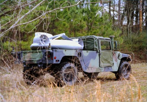
Transportation configuration.
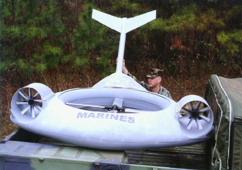
Deployment.
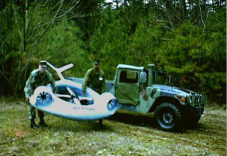
Man portable; deployable from unprepared surfaces.
The Drone also had capabilities that made it attractive for military applications, especially in low intensity conflicts and urban warfare . Note that such a drone would fill a needed void in locations where high altitude reconnaissance from assets such as Predator only provide the “"big picture” from above, but do not allow one to look into windows, fly into parking decks, breach obstacles, or perch on a building roof as a sentry. A militarized version of the drone known as Dragon Stalker was conceived and mocked up to illustrate its portability in the battlefield. A powered wind tunnel model was constructed to verify flight envelope analyses.
Dragon Stalker: small unit reconnaissance and fire support UAV
Dragon Stalker was a light weight twin-engine VTOL drone design capable of one-engine-inoperative flight. Due to its small footprint, it could operate from shipboard without occupying significant deck space (edge stackable), or it could be transported by small military vehicles. Dragon Stalker could be deployed from its shipping configuration by folding down its tail and locking it into place. To war-fighters could easily handle Dragon Stalker which when fueled and fitted with a payload, weighed under 200 pounds. Dragon Stalker was designed to be fully autonomous, being directed by high-level commands from the war-fighters' hand-held terminal ("takeoff", "go to waypoint Tango-Sierra-2.0", "hold at 90 feet AGL"). Dragon Stalker had a shrouded propulsors which not only afforded safety when deployed in proximity to personnel and vehicles, but they enhanced survivability in urban war zones where wire strikes are a particular threat to rotary wing vehicles. Special attention to noise control through absorptive and active methods gave Dragon Stalker the potential to be one of the quietest rotary wing drones in existence. Twin-engine reliability and an affordable design made Dragon Stalker a better idea than currently adopted approaches to small unit surveillance.
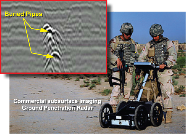
Remote Detection of Buried Natural Gas Leaks with Ground Penetration Radar (GPR)
[25] In 1985 and 1986 Robert Michelson directed a study at the Georgia Tech Research Institute through a contract sponsored by the Gas Research Institute (GRI), under a subcontract to the Philadelphia Electric Company (PECo).
Natural gas leaks occurring in buried distribution systems have caused concern within the utility industry due to the potential for environmental and safety problems which can result from even small volume leaks. Deaths and destruction of private property have occurred due to the formation of natural gas leaks in urban areas. To protect the public, utilities have instituted planned surveys of their gas distribution systems. Several methods are used to detect buried leaks. These techniques include vegetation surveys and above-ground surveys using portable gas detectors. Once gas is detected, "bar holes" are drilled in an effort to locate the specific region of the leak. Having found the probable leak location, a crew will excavate the site. An experienced leak pinpointing crew will fail to find the leak position 10% to 20% of the time, thereby requiring excavation of an adjacent site. The inaccuracy of location can often be attributed to ducting of the gas away from the actual region of the leak as a result of soil stratification or even the low resistance path caused by the distribution pipe-soil interface. Whatever the cause, the cost to the utility for a "dry hole" excavation can be as much as $1,500 depending on the area and surface preparation (pavement) which must be disturbed and restored. This is a serious cost to the industry when it is considered that it estimated 800,000 leaks are repaired in the U.S. annually.
There is an obvious need for a quick and accurate method of detecting not just the presence of a natural gas leak but its location as well. To this end, numerous methods for leak pinpointing have been investigated, including ground penetration radar and acoustic techniques (both active and passive). Michelson's team investigated the major parameters associated with the remote detection of natural gas leaks from buried utility pipes by electromagnetic means. The results of this study indicated that the recommended near-term system configuration for the detection of buried natural gas leaks was a modified bistatic approach incorporating two monostatic pulsed instrumentation radar systems separated by a fixed distance and operating within a transmitted signal frequency range of 0.1 GHz to 3 GHz.
Data gathered during this study showed laboratory measurements of dielectric constant, loss tangent, and the resulting attenuation for non-permeable samples over a broad range of frequencies roughly approximating those contained within the bandwidth of commercially available impulse ground penetration radars.
One area of vital importance which was outside the scope of this study dealt with the effect of natural gas leaks on soil characteristics, specifically how the gas actually interacts with the soil in terms of migration, desiccation, and chemical transmutation. The medium through which the energy passes must be modeled and thoroughly understood to fully apreciate how electromagnetic energy (or any other source) can be used most effectively to detect buried gas leaks.

Radio-Acoustic Techniques for Non Line-of-Sight (NLOS) Sensing
[26][27] In 1992 Robert Michelson led the Georgia Tech Research Institute team of senior engineers and scientists to develop a non line-of-sight (NLOS) sensor. In land battle scenarios, the opponent that reveals himself first will often lose in an ensuing encounter. It is therefore imperative that ground forces conduct their mission without being visible to opposing sensors. Various techniques can be employed to make ground vehicles less observable (camouflage, radar-absorbing materials, exhaust coolers, etc.), but simple tactics such as the use of terrain masking are often more effective means of increasing the survivability of a ground vehicle than any ectophoretic or deceptive devices. A major drawback with the use of terrain masking is that it tends to work both ways: not only is the masked vehicle hidden from view, but the masking terrain serves to block the sensors on the masked vehicle, thereby effectively blinding it to approaching threats.
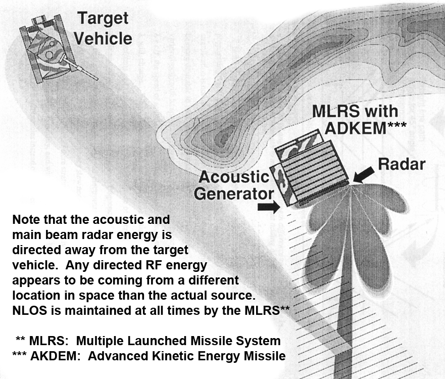
NLOS sensor scenario showing a masked vehicle interrogating an approaching threat vehicle.
Extendable antennas/sensor heads overcome the blocked sensor problem but, if active, must be low-probability-of-intercept (LPI) systems. Also, these line-of-site sensors can actually be a target designator for hostile anti-radiation munitions if they are detected.
An alternate approach is to use bistatic sensors such as remote antennas, UAVs, or surveillance aircraft to interrogate the battlefield and report what they see to terrain-masked forces. Unfortunately this can eliminate the element of surprise, may require air superiority in the region, and really precludes the possibility of individual ground vehicles operating autonomously (i.e., without having to rely on assets such as UAVs which may not be under their control).
The technique used by geophysicists[28] to measure the temperature profile of the atmosphere from the ground by tracking the speed of propagation of acoustic waves with radar was considered for adaptation as a NLOS sensor. Under funding from the Defense Advanced Research Projects Agency, (administered through the Picatinny Arsenal), this technique was investigated as having possible application to the direction of NLOS targets while maintaining a very low probability of intercept for the interrogating platform. Essentially, a radar may be made to "look around corners." The program led by Michelson, investigated the feasibility, physical limitations, and possible methods to augment the performance of this novel technique whereby a vehicle could remain fully masked to one side by an obstacle while being able to use radar to look around the masking obstruction, thereby maintaining low observability without loss of lethality and combat effectiveness. In addition, this technique was contrasted with other possible means of affecting an "around-the-the-corner" NLOS sensor.
The primary concept works by creating a three-dimensional acoustic diffraction grating in open air. This is done by horizontally transmitting a plane-wave acoustic signal of known period. The resulting periodic regions of compression and rarefaction in the atmosphere will propagate at a speed proportional to a number of factors, most predominantly temperature and wind speed. If a radar signal of an appropriately chosen wavelength (proportional in length to the acoustic wavelength) is transmitted into the advancing parallel acoustic wave fronts, then a minute amount of energy will be reflected from each wavefront. By choosing the periods of the acoustic and radar transmissions correctly, the reflected electromagnetic contribution from each acoustic wavefront will add constructively and coherently (Bragg principal) to create a redirected electromagnetic beam propagating at an angle according to Snell's law.
Study results indicated that augmented NLOS sensing based on radio-acoustic detection principles is possible with detection probabilities exceeding 90%, but only for ranges of 30 to 50 m under ideal environmental conditions. The primary limitations on range performance derived from the lack of return signal energy as a result of two factors:
the small density gradient existing between regions of sound-compressed and sound-rarefied air or and,
the lack of focusing provided by acoustic plane waves as opposed to that observed in monostatic radio-acoustic sounding scenarios which employ spherical acoustic waves to successfully sense at long ranges (kilometers).
Results showed that various enhancement techniques can drastically improve the performance of the radio-acoustic and NLOS sensor, but at the expense of covertness and in some cases degraded mobility.
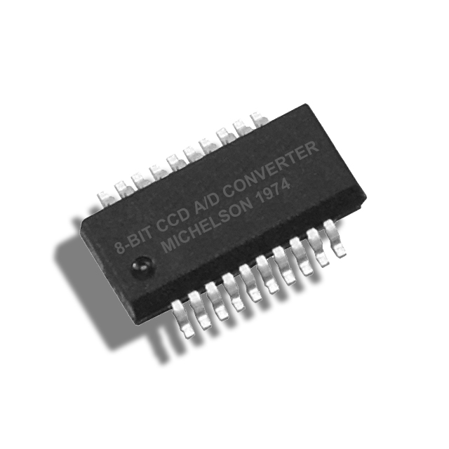
Charge-Coupled Devices for Analog-to-Digital Conversion
Robert Michelson's thesis [29] topic was the design of a novel analog-to-digital converter using charge-coupled devices.
Charge coupling, having been introduced in the late 60s, was a relatively new concept in metal-oxide semiconductor (MOS) technology at the time this thesis was written. Charge coupling provides the basic functions of data storage and transfer of both digital and analog data [30]. In addition, charge-coupled devices feature the principal advantages of presently existing MOS technology such as the basic fabrication steps, small surface area, and low power consumption.
Charge Coupled Devices (CCD) operate by transferring quantities of charge between potential wells created in a doped semiconductor material just below the semiconductor-insulator interface. These potential wells are actually inversion layers formed in the semiconductor material when a positive voltage is applied to an electrode above the insulator. Since the electrode is electrically insulated from the semiconductor material, an electrostatic field is produced which repels majority carriers (holes) and attracts minority carriers (electrons). Once an inversion layer has been established, charge can be injected into the potential well by any method that is capable of creating minority carriers. A sufficiently large positive voltage applied to the electrode will induce avalanche breakdown in the semiconductor material. During the avalanche breakdown, electrons are literally ripped from the outer shells of the substrate atoms nearest the semiconductor-insulator interface where the electrostatic fields are most intense. These liberated electrons then are held within the potential well created by the positive voltage on the electrode, and constitute an input to that well. Another input technique for entering charge is to create an N-region in the P-substrate which will act as a source of minority carriers. Applying a bias to the resulting P-N Junction while an inversion region is present nearby, will result in conduction of minority carriers from the N-region to the potential well. These quantities of charge that accumulate within the potential wells are referred to as "packets", and can be used to represent either analog or digital information. A third technique is to generate minority carriers within the semiconductor by exposing it to localized electromagnetic radiation (especially that falling within the visible range). Those minority carriers generated within a diffusion length of the potential well will accumulate in the well in proportion to the photon density.
When several elements are placed in a row on a common substrate, a charge packet in the first potential well can be made to propagate sequentially from well to well. In general, a two-phase clock can be used to achieve unidirectional movement; however, if a three-phase clock is used, bidirectional movement as possible. CCDs have found their greatest utility as video elements in cameras where impinging light is captured in an array of potential wells within a substrate and then clocked out of the array.
The results of this thesis showed that an 8-bit CCD-A/D could be designed that incorporates the desirable properties of several conversion techniques. A simulation program permitted the evaluation of the CCD-A/D design as a function of temperature, transfer efficiency, and clock rate. The simulation results showed that the effects of temperature and clock rates are closely related.
Transfer efficiency was found to be of less importance due to the relatively short delay lines employed in the converter. Data was obtained from the simulation program for a wide range of temperature-clock rate combinations. This data revealed regions of operation subject to given sets of constraints.
Analysis of the time constraints associated with the various components showed that the maximum theoretical conversion time was approximately 215 ns (slow by today's standards). The CCD-A/D converter was faster than many successive approximation schemes of the early 1970s, but somewhat slower than state-of-the-art parallel converters of the time.
Economically, a monolithic 8-bit CCD-A/D was shown to be comparable in chip area to standard TTL MSI, and it was therefore estimated that a CCD-A/D such as this would also be of comparable cost and production quantities.
As well as demonstrating utility, versatility, and potential economy, it was shown that the power requirements for a monolithic CCD-A/D converter would be approximately 2 mW, or a reduction of 500 times the power required for 1970s vintage converters. This, coupled with its small size and good speed/cost ratio, made the CCD-A/D converter a viable state-of-the-art alternative to then present A/D converters.
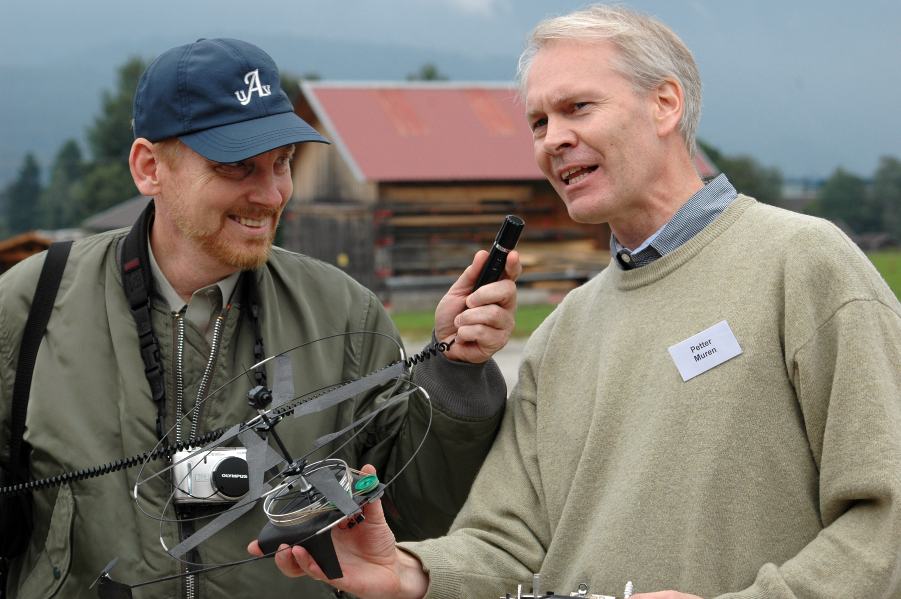
Prof. Michelson conducting an interview at the U.S. Army-sponsored "1st US-European Micro Air Vehicle Competition/Demonstration" in Garmisch Germany.
Design of Technology Demonstrations and Assessment of Micro Air Vehicle Technologies
Prof. Michelson has been a consultant to the U.S. Army and the Indian Ministry of Defence, responsible for defining the rules for and helping to organize the 1st U.S.-Asian Micro Air Vehicle Demonstration in Agra India (2008).[31][32] He performed similar duties for the U.S. Army in defining the 1st US-European Micro Air Vehicle Competition/Demonstration in Garmisch Germany (2005).[33] Michelson is often consulted regarding technology demonstrations, especially those having to do with aerial robotics, because of his unique experience in conducting successful events such as the International Aerial Robotics Competition for which he has been the creator and organizer for more than two decades. Michelson participated in the initial formulation of the DARPA Grand Challenge as a consultant, as well as advising the Canadian UVS community during their attempts to create a national collegiate competition to detect and combat improvised explosive devices (IED).
REFERENCES
- Michelson, R.C., "Tracking of the Florida Manatee,” ISA Transactions, Vol. 21, No. 1, 1982, pp. 79 - 85
- Michelson, R.C., “The Automated Remote Tracking of the Florida Manatee (Trichechus manatus ),” Proceedings of the 1981 IEEE SOUTHEASTCON, Huntsville, Alabama, April 1981, pp. 96 - 100
- Michelson, R.C., “Tracking of the Florida Manatee (Trichechus manatus ),” Proceedings of the 18th Annual Rocky Mountain Bioengineering Symposium, Laramie, Wyoming, April 1981
- Michelson, R.C., Breedlove, J., Jenkins, H.H., “Automated Tracking of the Florida Manatee (Trichechus manatus),” Final Report No. NAS10-9097-F, June 1978
- Sjoberg, E., Michelson, R.C., “Environment and Radar Operation Simulator,” Proceedings of the NAAG Panel XIV (EW) Group, Brussels, Belgium (invited paper), January 1978
- Sjoberg, E., Cole, S., Michelson, R.C., “Environment and Radar Operation Simulator,” Proceedings of the Sixteenth Annual U.S. Army Operation Research Symposium (AORS XVI), 12-14 October 1977, Fort Lee, Virginia
- Sjoberg, E.S., Cole, S.N., Flynt, E.R., Michelson, R.C., Vining, T.L., “Environment and Radar Operation Simulator,” ECOM-74-0272-F, Final Report, September 1977
- Butterworth, C., Michelson, R.C., Wallace, T., “Ka-Band Linear ECM Source (KABLES),” Final Report No. F33615-81-C-1530-F, June 1984
- Michelson, R.C., “Advanced Vehicle Control Systems,” Proceedings of the Workshop on Intelligent Vehicle Highway Systems and Advanced Transportation Technologies, Atlanta, Georgia, July 14 - 16, 1991
- "Battery State of Charge Detector with Rapid Charging Capability and Method", USPO number = 6,094,033, 7/25/2000
- Brazell, J., Michelson, R.C., “Automatic Control of a Truck-Mounted Drill Rig,” presented at the International Symposium on Mine Mechanization and Automation, Colorado School of Mines, Golden, CO, June 10 - 13, 1991
- Brazell, J., Michelson, R.C., “Automation of a Truck-Mounted Drill Rig,” Proceedings of the American Society of Civil Engineers, Cambridge, Massachusetts, April 13 - 16, 1991, pp. 272-277
- Michelson, R.C., Brooks, R., Scheer, J.A., Butterworth, C., et al, “Direct Support and General Support Maintenance Manual for the Georgia Tech Coherent Repeater,” April 1982
- Michelson, R.C., Brooks, R., Scheer, J.A., Butterworth, C., et al, "Operator’s Training and Maintenance Manual for the Georgia Tech Coherent Repeater,” April 1982
- http://pdv.cs.tu-berlin.de/MARVIN/index.html , "Multi-purpose Aerial Robot Vehicles with Intelligent Navigation", Technische Universität Berlin, 10-23-2007, accessdate=01-23-2009
- Michelson, R.C., Williamson, F.R., Brooks, R., “Indirect Fire Simulator- Cue System Development,” Final Report, Contract No. DAAG08-78-C-0191-F, January 1980
- Michelson, R.C., Brooks, R., Taylor, K.P., “Sonar Scan Converter,” Final Report No. N00612-79-D-8004-HR53-F, June 1984
- Irwin, D., Brooks, R., Michelson, R.C., et al, “Advanced Surveillance and Target Acquisition Radar (ASTAR) Prototype,” Final Report on Contract No. DAAK20-82-C-0144, February 1983
- Colozza, A., Michelson, R.C., et al., “Planetary Exploration Using Biomimetics - An Entomopter for Flight on Mars,” Phase II Final Report, NASA Institute for Advanced Concepts Project NAS5-98051, October 2002
- “Entomopter and Method for Using Same”, U.S. Patent No. 6,082,671, July 4, 2000
- “Reciprocating Chemical Muscle (RCM) and Method for Using Same”, U.S. Patent No. 6,446,909, September 10, 2002
- Englar, Robert J., Smith, Marilyn J., Kelley, Sean M., and Rover III, Richard C., “Development of Circulation Control Technology for Application to Advanced Subsonic Transport Aircraft, Part I: Airfoil Development” AIAA Paper No. 93-0644, Log No. C-8057, published in AIAA Journal of Aircraft, Vol. 31, No. 5, pp. 1160-1168, Sept-Oct 1994
- Englar, Robert J., Smith, Marilyn J., Kelley, Sean M., and Rover III, Richard C., “Development of Circulation Control Technology for Application to Advanced Subsonic Transport Aircraft, Part II: Transport Application” AIAA Paper No. 93-0644, Log No. C-8058, published in AIAA Journal of Aircraft, Vol. 31, No. 5, pp. 1169-1177, Sept-Oct 1994
- Colozza, A., Michelson, R.C., et al., “Planetary Exploration Using Biomimetics - An Entomopter for Flight on Mars,” Phase II Final Report, NASA Institute for Advanced Concepts Project NAS5-98051, October 2002
- Michelson, R.C., Alford, S.T., Echard, J.D., Gostin, L.L., Lunsford, G.H., Scheer, J.A., “Remote Detection of Natural Gas Leaks from Buried Utility Pipes by Electromagnetic Means,” Final Report, Contract No. GRI-50084-252-112 (subcontract to the Philadelphia Electric Company; prime to the Gas Research Institute), June 1986
- Michelson, R.C., Ahuja, K.K., Scheer, J.A., et al, "Feasibility of Applying Radio-Acoustic Techniques to Non Line-of-Sight Sensing,” 15th AIAA Aeroacoustics Conference, Long Beach, CA, October 25 - 27, 1993
- Michelson, R.C., Ahuja, K.K., Scheer, J.A., et al, “Non Line-of-Sight Sensor,” DARPA, A-9271 Final Report, Contract DAAA91-92-C-0098, March 1993
- May, P.T., Strauch, R.G., Moran, K.P., and Ecklund, W.L., "Temperature Sounding by RASS with Wind Profiler Radars: A Preliminary Study," IEEE Transactions on Geoscience and Reote Sensing, Vol. 28, No. 1, January 1990, pp 19-27
- Michelson, R.C., “Charge-Coupled Devices for Analog-to-Digital Conversion,” Georgia Institute of Technology, November 1974, pages = 76
- Barbie, D.F., "Charge-Coupled Devices, " The University of Michigan Engineering Summer Conference on Advanced Infrared Technology, July 16-20, 1973
- http://www.nal.res.in/MAV08/orgcomitte.htm, MAV08 Organizing Committee, accessdate=03-19-2009
- 1st US-Asian Demonstration and Assessment of Micro Aerial Vehicle (MAV) and Unmanned Ground Vehicle (UGV) Technology - Schedule of Events, Abstracts and Profiles, 1st US-Asian Demonstration and Assessment of Micro Aerial Vehicle (MAV) and Unmanned Ground Vehicle (UGV) Technology, National Aerospace Laboratories, ADRDE, US Army RDECOM, March 10-15, 2008, (also accessible on the internet at: http://www.nal.res.in/MAV08/MAV-pdf/mavabstracts.pdf), accessdate=03-22-2009, pages = 70
- http://aeromav.free.fr/MAV05/aeromav/vitae/, title=MAV05 organizers' vitae from remaining documents at MAV05 website, accessdate=03-19-2009}}
Transportation configuration.
Deployment.
Man portable; deployable from unprepared surfaces.
The Drone also had capabilities that made it attractive for military applications, especially in low intensity conflicts and urban warfare . Note that such a drone would fill a needed void in locations where high altitude reconnaissance from assets such as Predator only provide the “"big picture” from above, but do not allow one to look into windows, fly into parking decks, breach obstacles, or perch on a building roof as a sentry. A militarized version of the drone known as Dragon Stalker was conceived and mocked up to illustrate its portability in the battlefield. A powered wind tunnel model was constructed to verify flight envelope analyses.
Dragon Stalker: small unit reconnaissance and fire support UAV Dragon Stalker was a light weight twin-engine VTOL drone design capable of one-engine-inoperative flight. Due to its small footprint, it could operate from shipboard without occupying significant deck space (edge stackable), or it could be transported by small military vehicles. Dragon Stalker could be deployed from its shipping configuration by folding down its tail and locking it into place. To war-fighters could easily handle Dragon Stalker which when fueled and fitted with a payload, weighed under 200 pounds. Dragon Stalker was designed to be fully autonomous, being directed by high-level commands from the war-fighters' hand-held terminal ("takeoff", "go to waypoint Tango-Sierra-2.0", "hold at 90 feet AGL"). Dragon Stalker had a shrouded propulsors which not only afforded safety when deployed in proximity to personnel and vehicles, but they enhanced survivability in urban war zones where wire strikes are a particular threat to rotary wing vehicles. Special attention to noise control through absorptive and active methods gave Dragon Stalker the potential to be one of the quietest rotary wing drones in existence. Twin-engine reliability and an affordable design made Dragon Stalker a better idea than currently adopted approaches to small unit surveillance.
Remote Detection of Buried Natural Gas Leaks with Ground Penetration Radar (GPR)
[25] In 1985 and 1986 Robert Michelson directed a study at the Georgia Tech Research Institute through a contract sponsored by the Gas Research Institute (GRI), under a subcontract to the Philadelphia Electric Company (PECo).
Natural gas leaks occurring in buried distribution systems have caused concern within the utility industry due to the potential for environmental and safety problems which can result from even small volume leaks. Deaths and destruction of private property have occurred due to the formation of natural gas leaks in urban areas. To protect the public, utilities have instituted planned surveys of their gas distribution systems. Several methods are used to detect buried leaks. These techniques include vegetation surveys and above-ground surveys using portable gas detectors. Once gas is detected, "bar holes" are drilled in an effort to locate the specific region of the leak. Having found the probable leak location, a crew will excavate the site. An experienced leak pinpointing crew will fail to find the leak position 10% to 20% of the time, thereby requiring excavation of an adjacent site. The inaccuracy of location can often be attributed to ducting of the gas away from the actual region of the leak as a result of soil stratification or even the low resistance path caused by the distribution pipe-soil interface. Whatever the cause, the cost to the utility for a "dry hole" excavation can be as much as $1,500 depending on the area and surface preparation (pavement) which must be disturbed and restored. This is a serious cost to the industry when it is considered that it estimated 800,000 leaks are repaired in the U.S. annually.
There is an obvious need for a quick and accurate method of detecting not just the presence of a natural gas leak but its location as well. To this end, numerous methods for leak pinpointing have been investigated, including ground penetration radar and acoustic techniques (both active and passive). Michelson's team investigated the major parameters associated with the remote detection of natural gas leaks from buried utility pipes by electromagnetic means. The results of this study indicated that the recommended near-term system configuration for the detection of buried natural gas leaks was a modified bistatic approach incorporating two monostatic pulsed instrumentation radar systems separated by a fixed distance and operating within a transmitted signal frequency range of 0.1 GHz to 3 GHz.
Data gathered during this study showed laboratory measurements of dielectric constant, loss tangent, and the resulting attenuation for non-permeable samples over a broad range of frequencies roughly approximating those contained within the bandwidth of commercially available impulse ground penetration radars.
One area of vital importance which was outside the scope of this study dealt with the effect of natural gas leaks on soil characteristics, specifically how the gas actually interacts with the soil in terms of migration, desiccation, and chemical transmutation. The medium through which the energy passes must be modeled and thoroughly understood to fully apreciate how electromagnetic energy (or any other source) can be used most effectively to detect buried gas leaks.
Radio-Acoustic Techniques for Non Line-of-Sight (NLOS) Sensing
[26][27] In 1992 Robert Michelson led the Georgia Tech Research Institute team of senior engineers and scientists to develop a non line-of-sight (NLOS) sensor. In land battle scenarios, the opponent that reveals himself first will often lose in an ensuing encounter. It is therefore imperative that ground forces conduct their mission without being visible to opposing sensors. Various techniques can be employed to make ground vehicles less observable (camouflage, radar-absorbing materials, exhaust coolers, etc.), but simple tactics such as the use of terrain masking are often more effective means of increasing the survivability of a ground vehicle than any ectophoretic or deceptive devices. A major drawback with the use of terrain masking is that it tends to work both ways: not only is the masked vehicle hidden from view, but the masking terrain serves to block the sensors on the masked vehicle, thereby effectively blinding it to approaching threats.
NLOS sensor scenario showing a masked vehicle interrogating an approaching threat vehicle.
Extendable antennas/sensor heads overcome the blocked sensor problem but, if active, must be low-probability-of-intercept (LPI) systems. Also, these line-of-site sensors can actually be a target designator for hostile anti-radiation munitions if they are detected.
An alternate approach is to use bistatic sensors such as remote antennas, UAVs, or surveillance aircraft to interrogate the battlefield and report what they see to terrain-masked forces. Unfortunately this can eliminate the element of surprise, may require air superiority in the region, and really precludes the possibility of individual ground vehicles operating autonomously (i.e., without having to rely on assets such as UAVs which may not be under their control).
The technique used by geophysicists[28] to measure the temperature profile of the atmosphere from the ground by tracking the speed of propagation of acoustic waves with radar was considered for adaptation as a NLOS sensor. Under funding from the Defense Advanced Research Projects Agency, (administered through the Picatinny Arsenal), this technique was investigated as having possible application to the direction of NLOS targets while maintaining a very low probability of intercept for the interrogating platform. Essentially, a radar may be made to "look around corners." The program led by Michelson, investigated the feasibility, physical limitations, and possible methods to augment the performance of this novel technique whereby a vehicle could remain fully masked to one side by an obstacle while being able to use radar to look around the masking obstruction, thereby maintaining low observability without loss of lethality and combat effectiveness. In addition, this technique was contrasted with other possible means of affecting an "around-the-the-corner" NLOS sensor.
The primary concept works by creating a three-dimensional acoustic diffraction grating in open air. This is done by horizontally transmitting a plane-wave acoustic signal of known period. The resulting periodic regions of compression and rarefaction in the atmosphere will propagate at a speed proportional to a number of factors, most predominantly temperature and wind speed. If a radar signal of an appropriately chosen wavelength (proportional in length to the acoustic wavelength) is transmitted into the advancing parallel acoustic wave fronts, then a minute amount of energy will be reflected from each wavefront. By choosing the periods of the acoustic and radar transmissions correctly, the reflected electromagnetic contribution from each acoustic wavefront will add constructively and coherently (Bragg principal) to create a redirected electromagnetic beam propagating at an angle according to Snell's law.
Study results indicated that augmented NLOS sensing based on radio-acoustic detection principles is possible with detection probabilities exceeding 90%, but only for ranges of 30 to 50 m under ideal environmental conditions. The primary limitations on range performance derived from the lack of return signal energy as a result of two factors:
the small density gradient existing between regions of sound-compressed and sound-rarefied air or and,
the lack of focusing provided by acoustic plane waves as opposed to that observed in monostatic radio-acoustic sounding scenarios which employ spherical acoustic waves to successfully sense at long ranges (kilometers).
Results showed that various enhancement techniques can drastically improve the performance of the radio-acoustic and NLOS sensor, but at the expense of covertness and in some cases degraded mobility.
Charge-Coupled Devices for Analog-to-Digital Conversion
Robert Michelson's thesis [29] topic was the design of a novel analog-to-digital converter using charge-coupled devices.
Charge coupling, having been introduced in the late 60s, was a relatively new concept in metal-oxide semiconductor (MOS) technology at the time this thesis was written. Charge coupling provides the basic functions of data storage and transfer of both digital and analog data [30]. In addition, charge-coupled devices feature the principal advantages of presently existing MOS technology such as the basic fabrication steps, small surface area, and low power consumption.
Charge Coupled Devices (CCD) operate by transferring quantities of charge between potential wells created in a doped semiconductor material just below the semiconductor-insulator interface. These potential wells are actually inversion layers formed in the semiconductor material when a positive voltage is applied to an electrode above the insulator. Since the electrode is electrically insulated from the semiconductor material, an electrostatic field is produced which repels majority carriers (holes) and attracts minority carriers (electrons). Once an inversion layer has been established, charge can be injected into the potential well by any method that is capable of creating minority carriers. A sufficiently large positive voltage applied to the electrode will induce avalanche breakdown in the semiconductor material. During the avalanche breakdown, electrons are literally ripped from the outer shells of the substrate atoms nearest the semiconductor-insulator interface where the electrostatic fields are most intense. These liberated electrons then are held within the potential well created by the positive voltage on the electrode, and constitute an input to that well. Another input technique for entering charge is to create an N-region in the P-substrate which will act as a source of minority carriers. Applying a bias to the resulting P-N Junction while an inversion region is present nearby, will result in conduction of minority carriers from the N-region to the potential well. These quantities of charge that accumulate within the potential wells are referred to as "packets", and can be used to represent either analog or digital information. A third technique is to generate minority carriers within the semiconductor by exposing it to localized electromagnetic radiation (especially that falling within the visible range). Those minority carriers generated within a diffusion length of the potential well will accumulate in the well in proportion to the photon density.
When several elements are placed in a row on a common substrate, a charge packet in the first potential well can be made to propagate sequentially from well to well. In general, a two-phase clock can be used to achieve unidirectional movement; however, if a three-phase clock is used, bidirectional movement as possible. CCDs have found their greatest utility as video elements in cameras where impinging light is captured in an array of potential wells within a substrate and then clocked out of the array.
The results of this thesis showed that an 8-bit CCD-A/D could be designed that incorporates the desirable properties of several conversion techniques. A simulation program permitted the evaluation of the CCD-A/D design as a function of temperature, transfer efficiency, and clock rate. The simulation results showed that the effects of temperature and clock rates are closely related.
Transfer efficiency was found to be of less importance due to the relatively short delay lines employed in the converter. Data was obtained from the simulation program for a wide range of temperature-clock rate combinations. This data revealed regions of operation subject to given sets of constraints.
Analysis of the time constraints associated with the various components showed that the maximum theoretical conversion time was approximately 215 ns (slow by today's standards). The CCD-A/D converter was faster than many successive approximation schemes of the early 1970s, but somewhat slower than state-of-the-art parallel converters of the time.
Economically, a monolithic 8-bit CCD-A/D was shown to be comparable in chip area to standard TTL MSI, and it was therefore estimated that a CCD-A/D such as this would also be of comparable cost and production quantities.
As well as demonstrating utility, versatility, and potential economy, it was shown that the power requirements for a monolithic CCD-A/D converter would be approximately 2 mW, or a reduction of 500 times the power required for 1970s vintage converters. This, coupled with its small size and good speed/cost ratio, made the CCD-A/D converter a viable state-of-the-art alternative to then present A/D converters.